Columbia Formula Racing
Aero-Based Cooling via Nosecone Design
The Problem
Accumulator overheating during endurance runs
Cooling limited by poor airflow quality under the car
Existing nosecone caused flow separation and vortex losses
Under-floor air speed too low for effective convective cooling
The Challenge
Deliver clean, high-velocity airflow to the accumulator cooling surface
Improve cooling without adding fans or increasing drag
Maintain aerodynamic stability and rules compliance
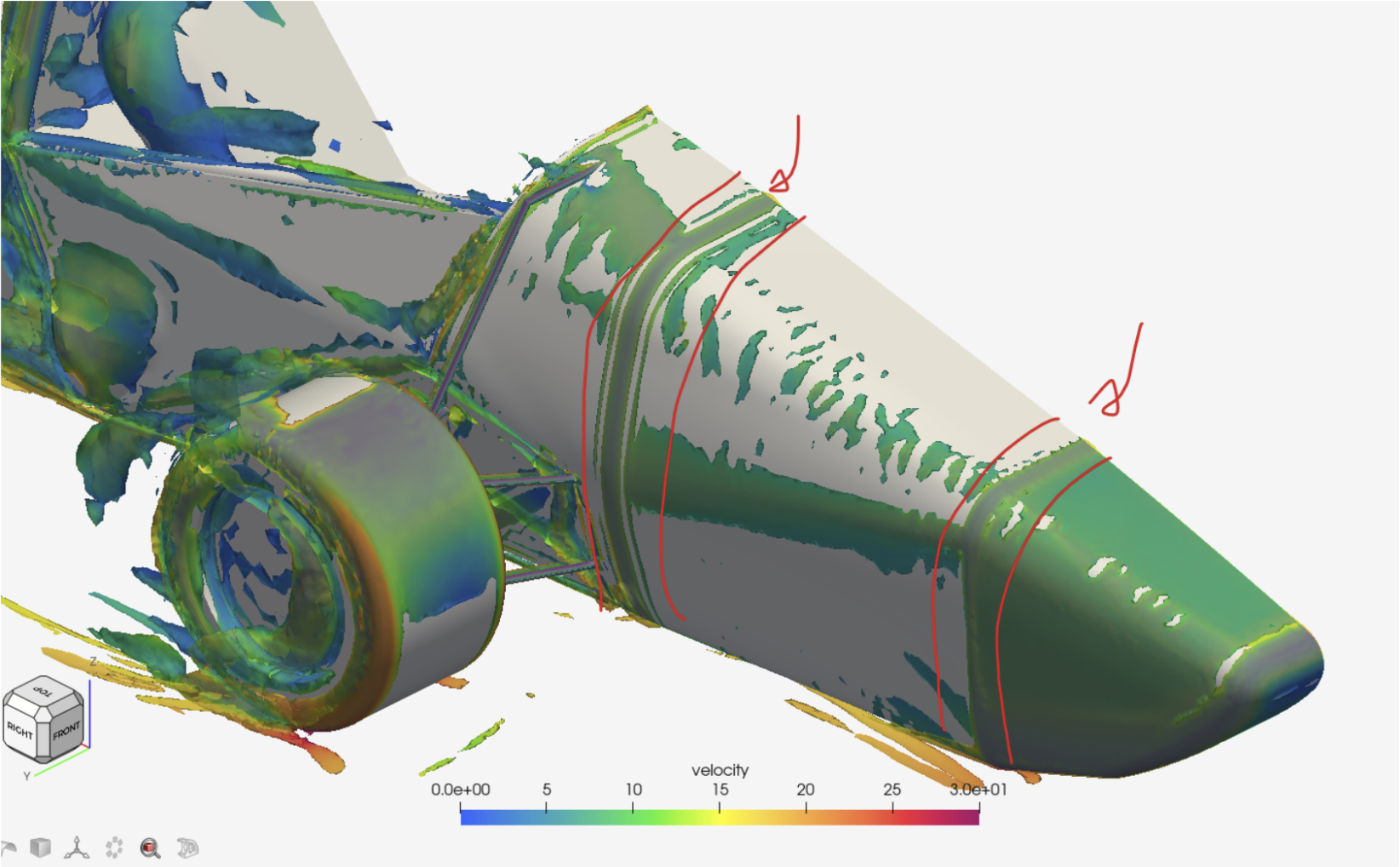
CFD: Vorticity shed by the previous nosecone, colored by velocity (m/s).
Note: Red annotations mark major sources of loss on the nosecone caused by inadequate geometry continuity
The Solution
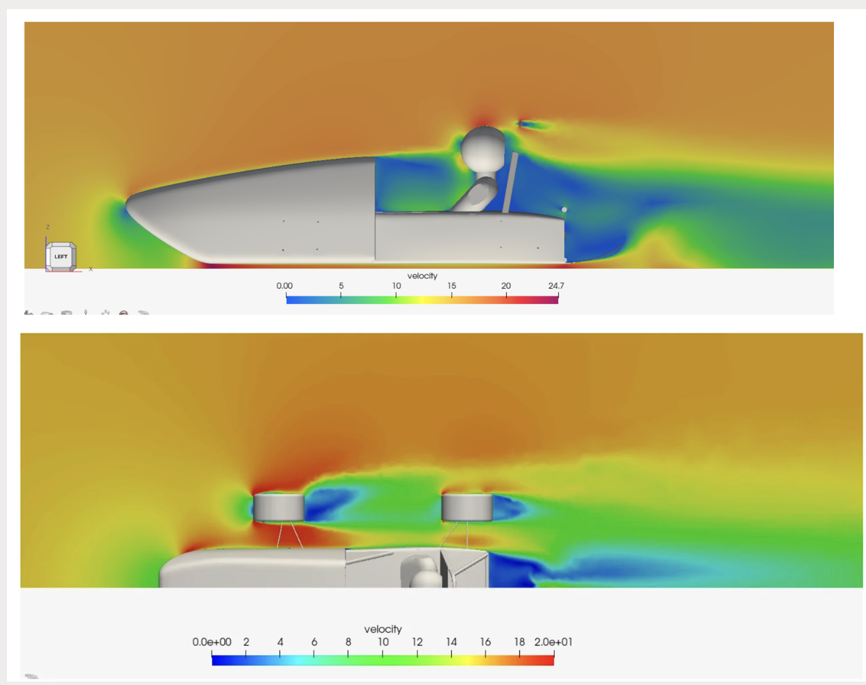
Fig. initial CFD to understand airflow behavior and guide design choices
Define Requirements
Estimated thermal load from the accumulator and identified air-side convection as the bottleneck
Defined airflow requirements: high-velocity, stable under-floor flow to reduce thermal resistance
Established aerodynamic constraints from FSAE rules and packaging limits
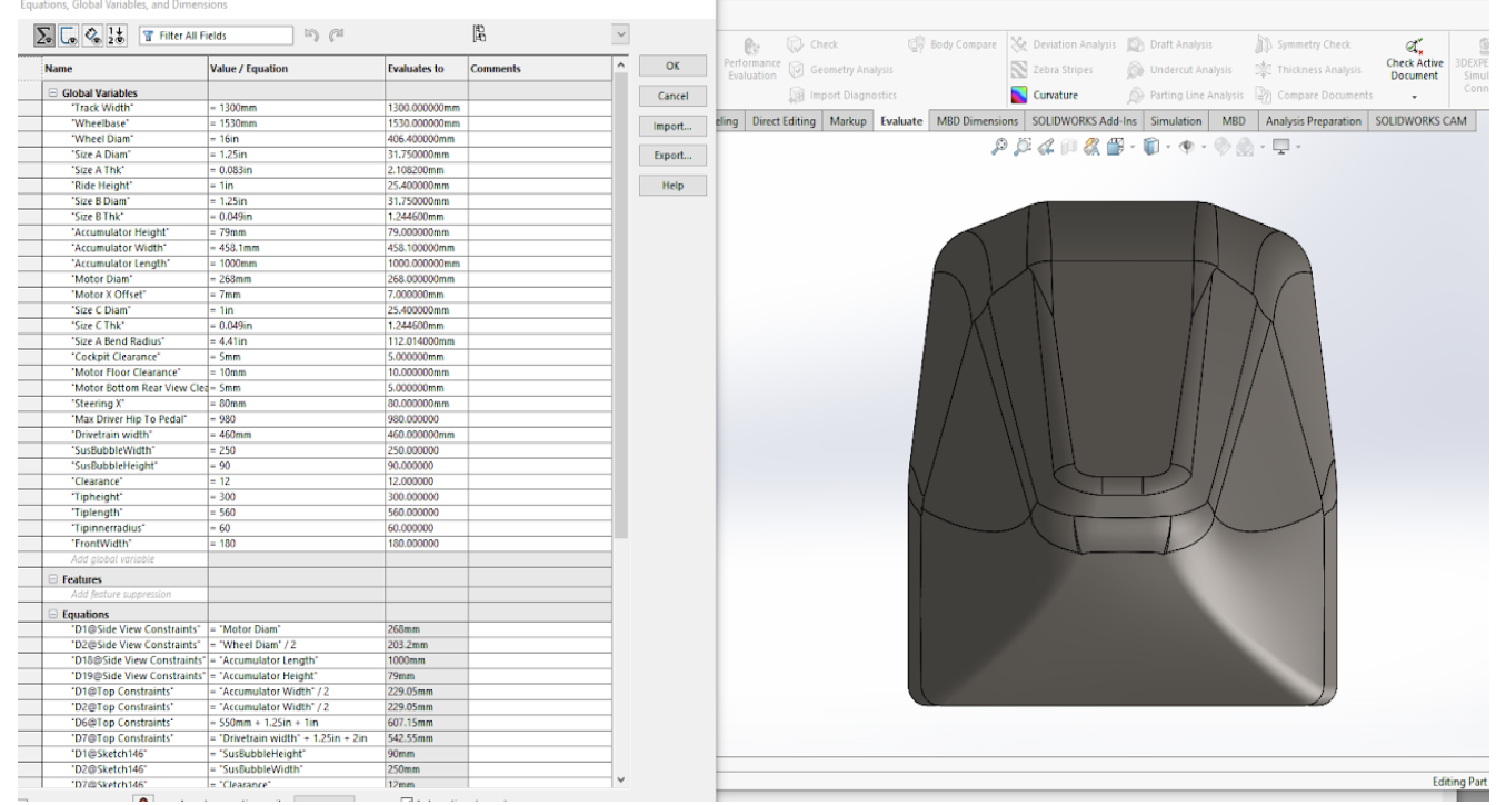
Fig. Parametric CAD of the Nosecone, variable geometry
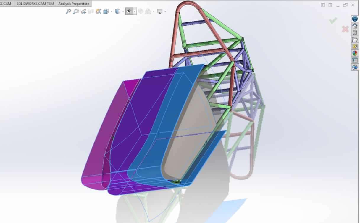
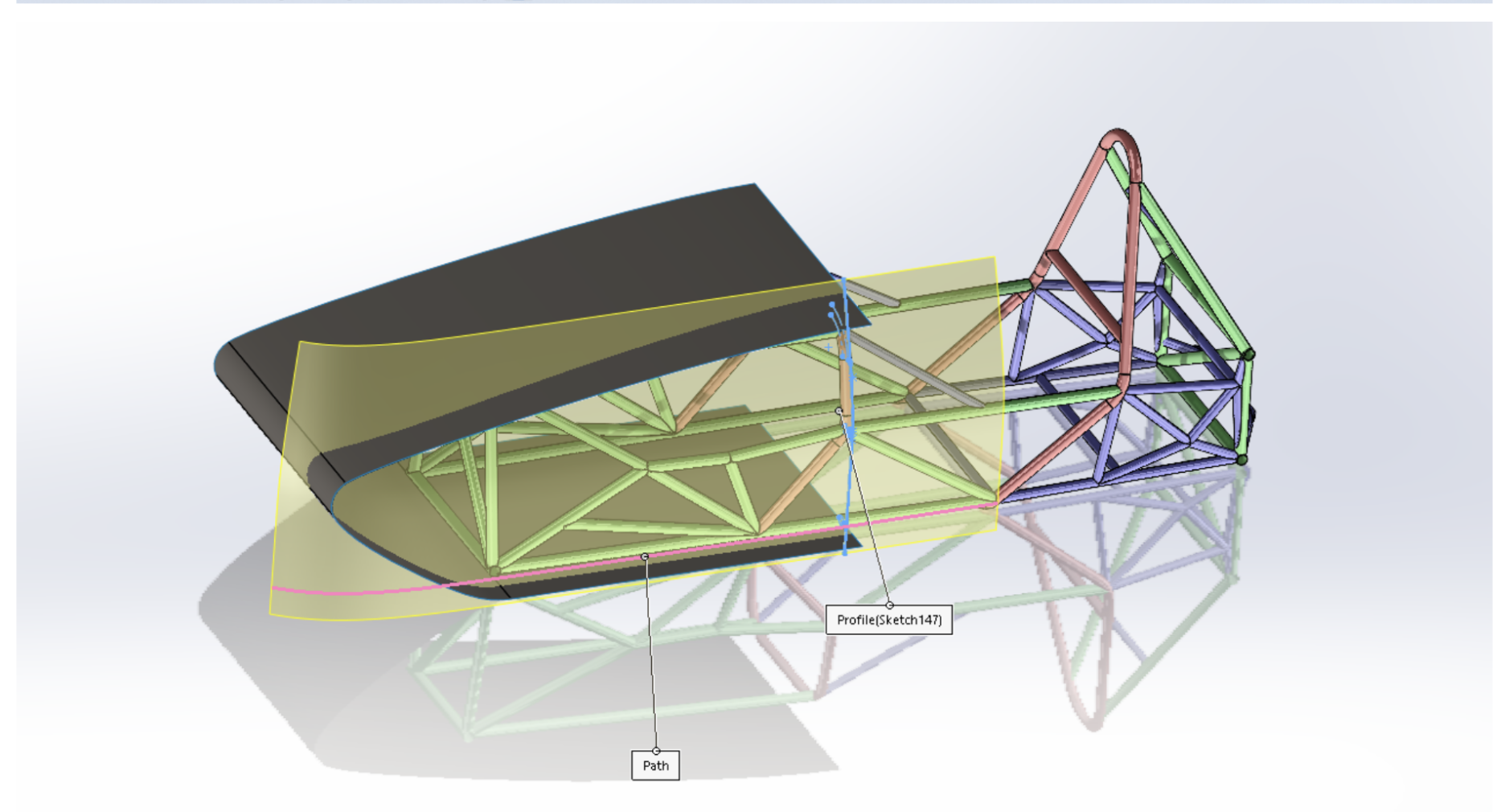
Fig. Surface Modeling, Nosecone
Iterative CFD-Driven Refinement
Used CFD to evaluate velocity fields, pressure distribution, and vorticity
Identified and eliminated geometry-induced flow losses
Tuned nosecone geometry to generate a controlled vortex for floor sealing
Iterated design until airflow to the undertray was clean, stable, and repeatable
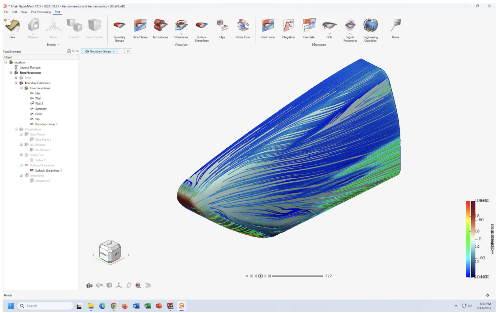
Fig. CFD, pressure gradient
Parametric Nosecone Design
Built a fully parametric SolidWorks model
Key variables included tip height, width, and inner radius
Used surface modeling with G2 continuity to maintain smooth airflow and prevent boundary layer disruption
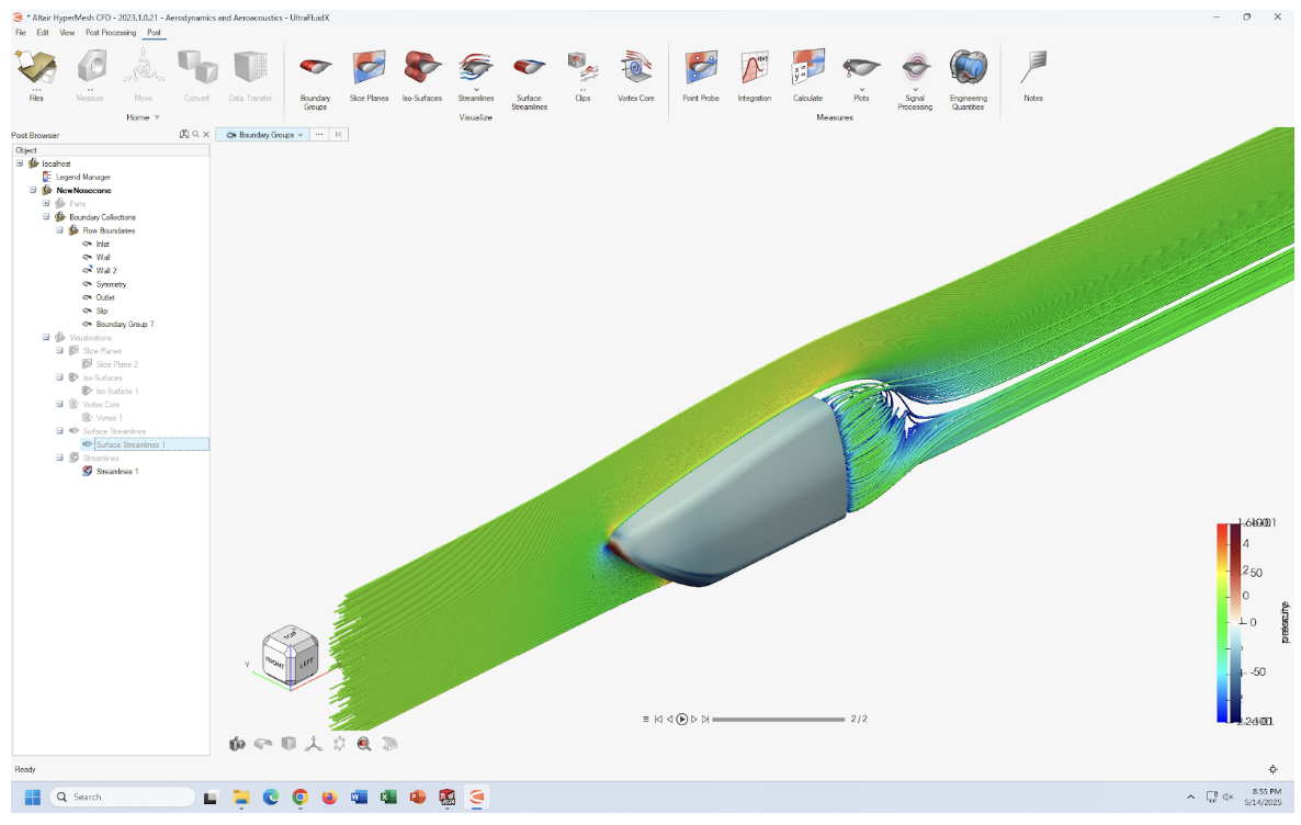
Fig. CFD, surface streamlines
The Impact
Thermal Performance
Significantly increased mass flow to the accumulator cooling zone
Enhanced convective heat rejection by delivering higher-velocity airflow to cooling surfaces
Aerodynamic Performance
Eliminated geometry-induced flow losses at the nosecone
Generated a controlled vortex for effective floor sealing
Improved under-floor airflow quality and diffuser performance
System-Level Impact
Increased under-floor downforce (~10%), improving aerodynamic stability
Delivered cleaner, more predictable airflow to downstream aero components
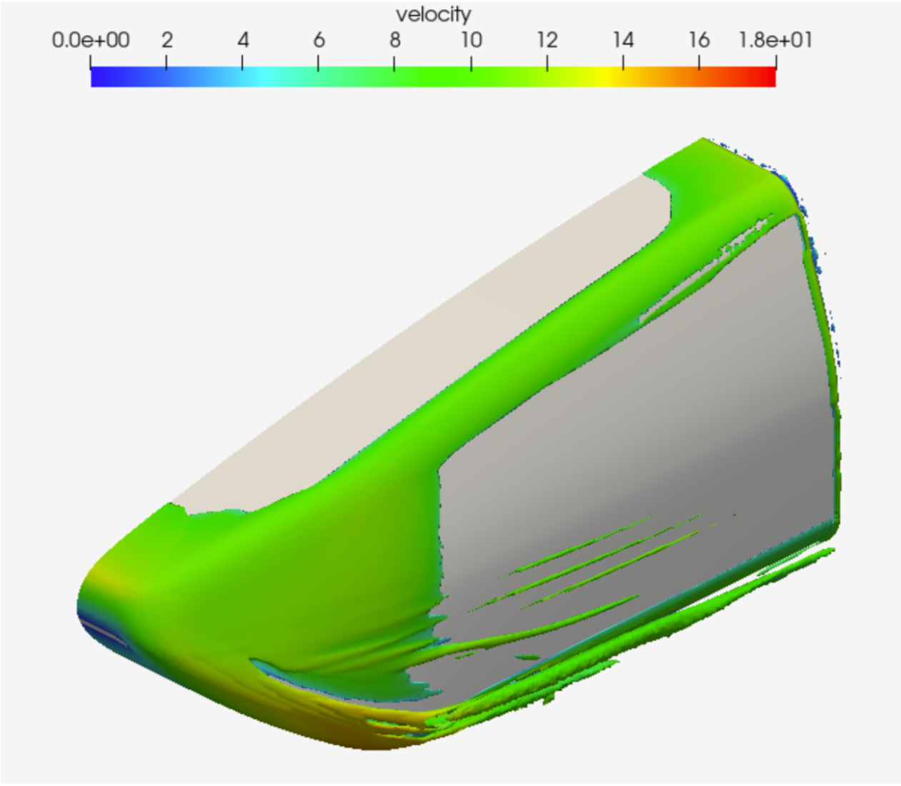
Fig. CFD, Isosurface for a curl of 500Hz, colored by velocity. Velocity is given in m/s.
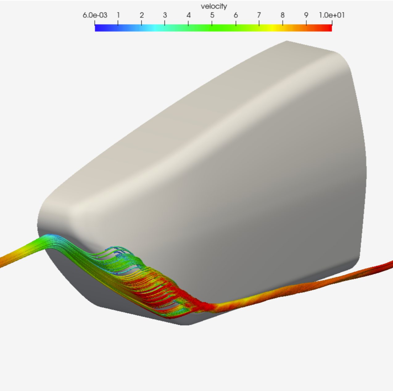
Fig. Velocity (m/s) streamlines highlighting the Y320 vortex
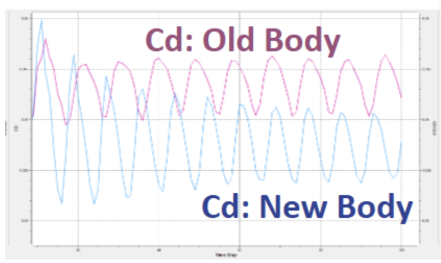
Fig. new design has reduced drag coefficient
Conclusion
In stark contrast to the previous nosecone, vortices are well-managed with no major geometry-induced losses
A strong, controlled vortex is intentionally shed from the bottom of the nosecone at y = 320 mm (Y320 vortex)
The Y320 vortex seals the under-floor region, preventing external turbulent flow from intruding into the accumulator cooling zone
Controlled vorticity cleans up downstream tire wake, improving diffuser flow quality
Overall, the redesigned nosecone produces purposeful, stable vorticity rather than chaotic losses, resulting in improved aerodynamic and thermal performance